Making the 20V Parkside charger silent
Prerequisites - What do we need
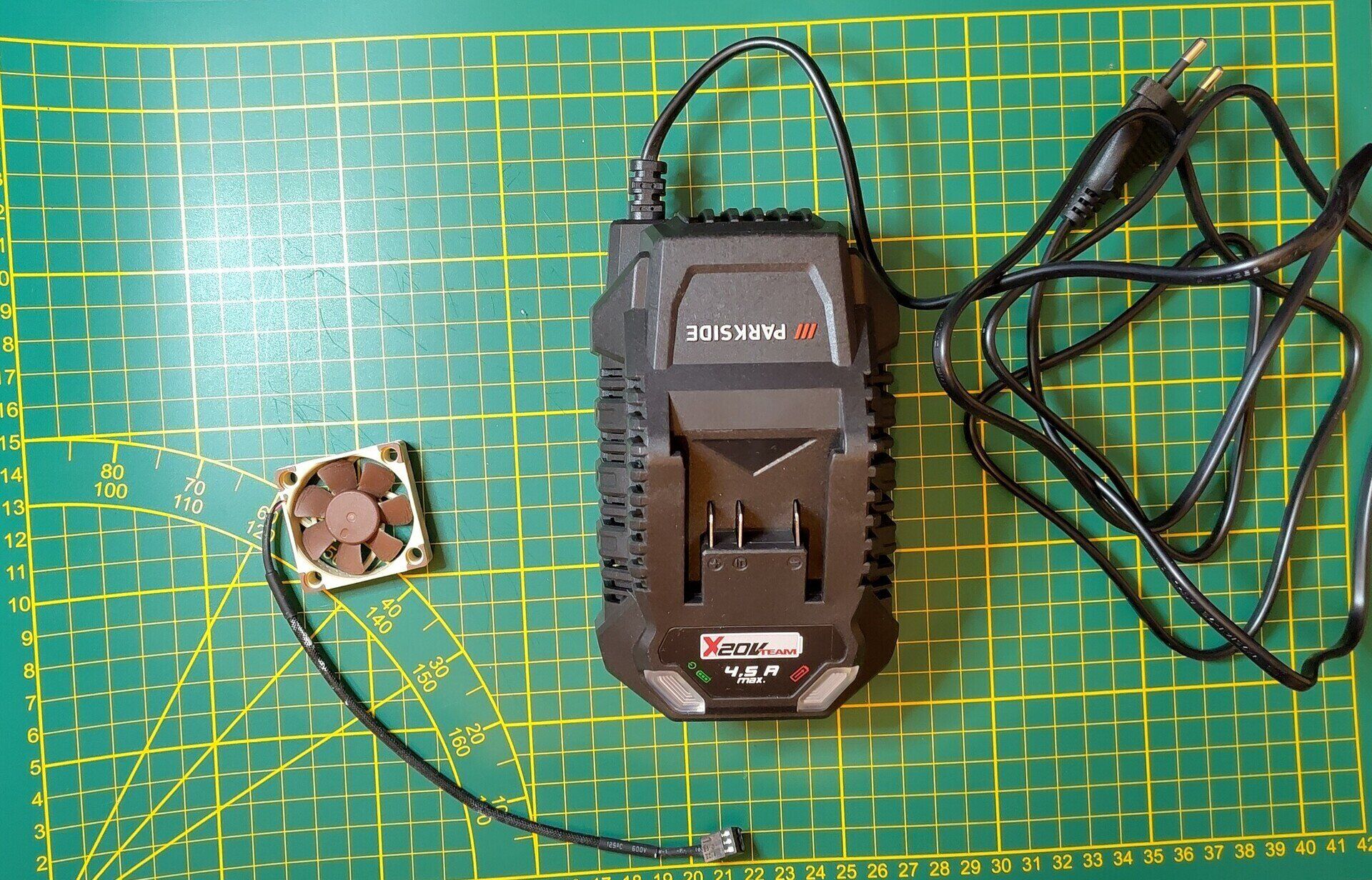
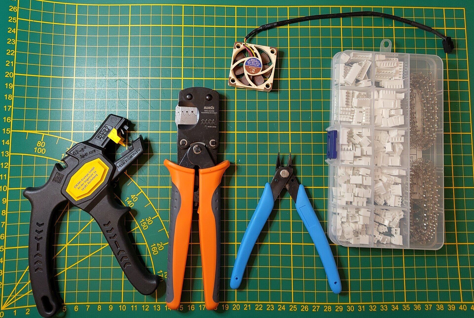
So before starting with this mod what parts and tools do we need:
| Part | Affiliate link* | Comments |
|---|---|---|
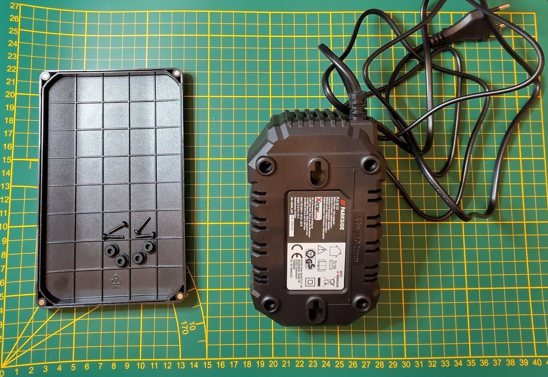
| Parkside 20V Charger | - | My model was the PLG20C3, but PLG20A3 should work, possibly older ones too, check if it is a 12V fan. |
| Noctua 4Ax10 | - | I went with a used one I picked up from Marktplaats (Dutch Craigslist). You can also use another 12V fan that is 40x10mm, you won’t need PWM or the Tach pin. |
| JST XH 2.54mm connector | JST connector set | - |
| JST crimping tool (IWS-3220M) | IWS-3220M with JST XH connectors IWS-3220M |
I really recommend getting a crimping tool like this, there are also more expensive versions available. |
| Cable stripper | Nameless version | I use a Jokari cable stripper that works one many different thicknesses, so if you’re willing to splurge get that one. But the one linked will also work fine. |
| Snipping tool | Flush cutting snipping tool | I assume you have one of these, just use one that can snip cables, I use the ones that came with my Creality 3D printer. |
| Heatshrinks | Heatshrinks set | I forgot to add these to the image but do include these, also have a heat source to shrink them, in a pinch isolation tape can work. |
*When you buy something with the affiliate link I receive a small commission.
So with all these tools and parts, which you can also see down below in the two images, we can start with the modification.
Step 1 - Open up the charger
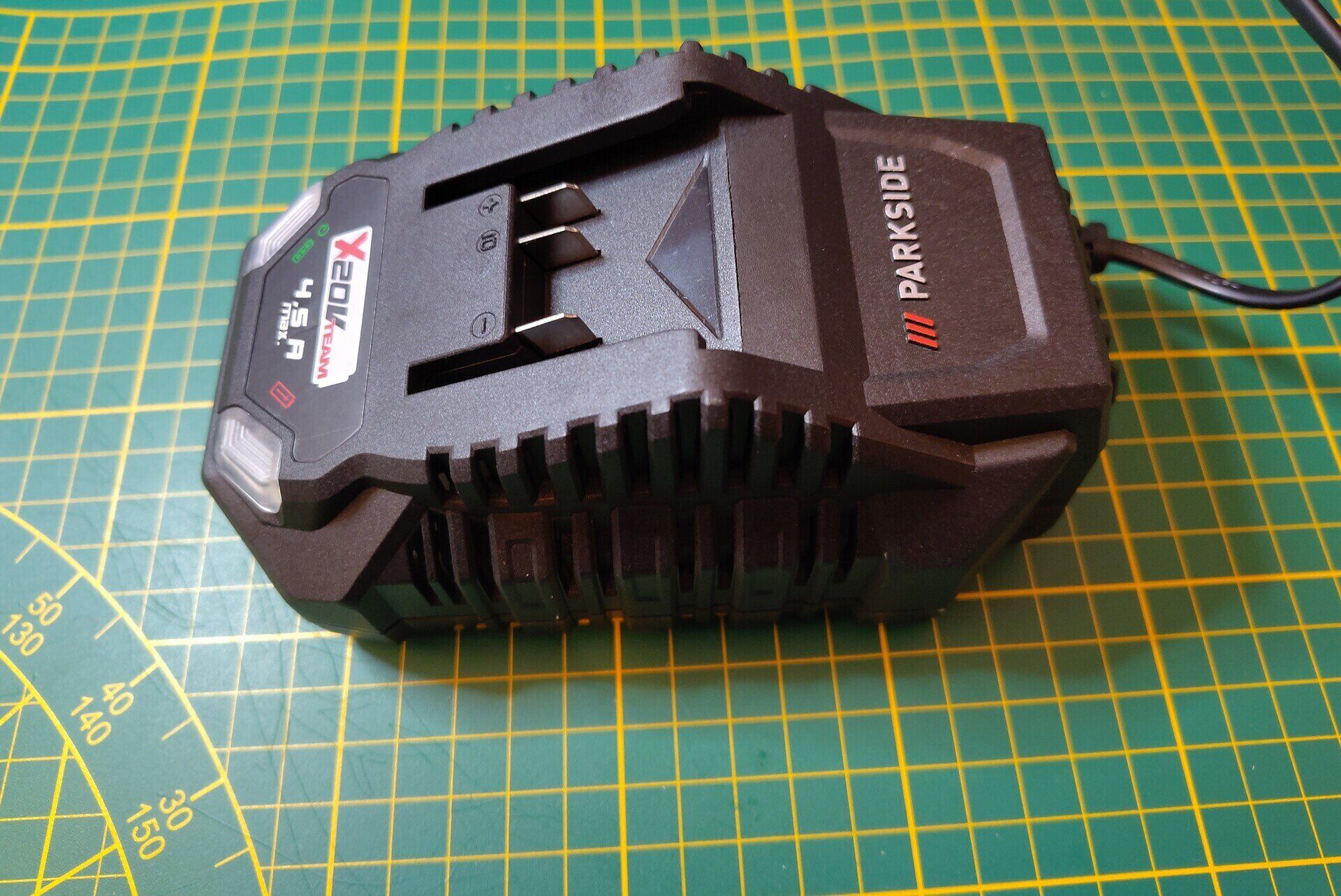
Let’s start with opening the charger, without saying make sure you disconnected the charger from the mains power, also make sure there is no battery connected. Now twist the charger to its backside.
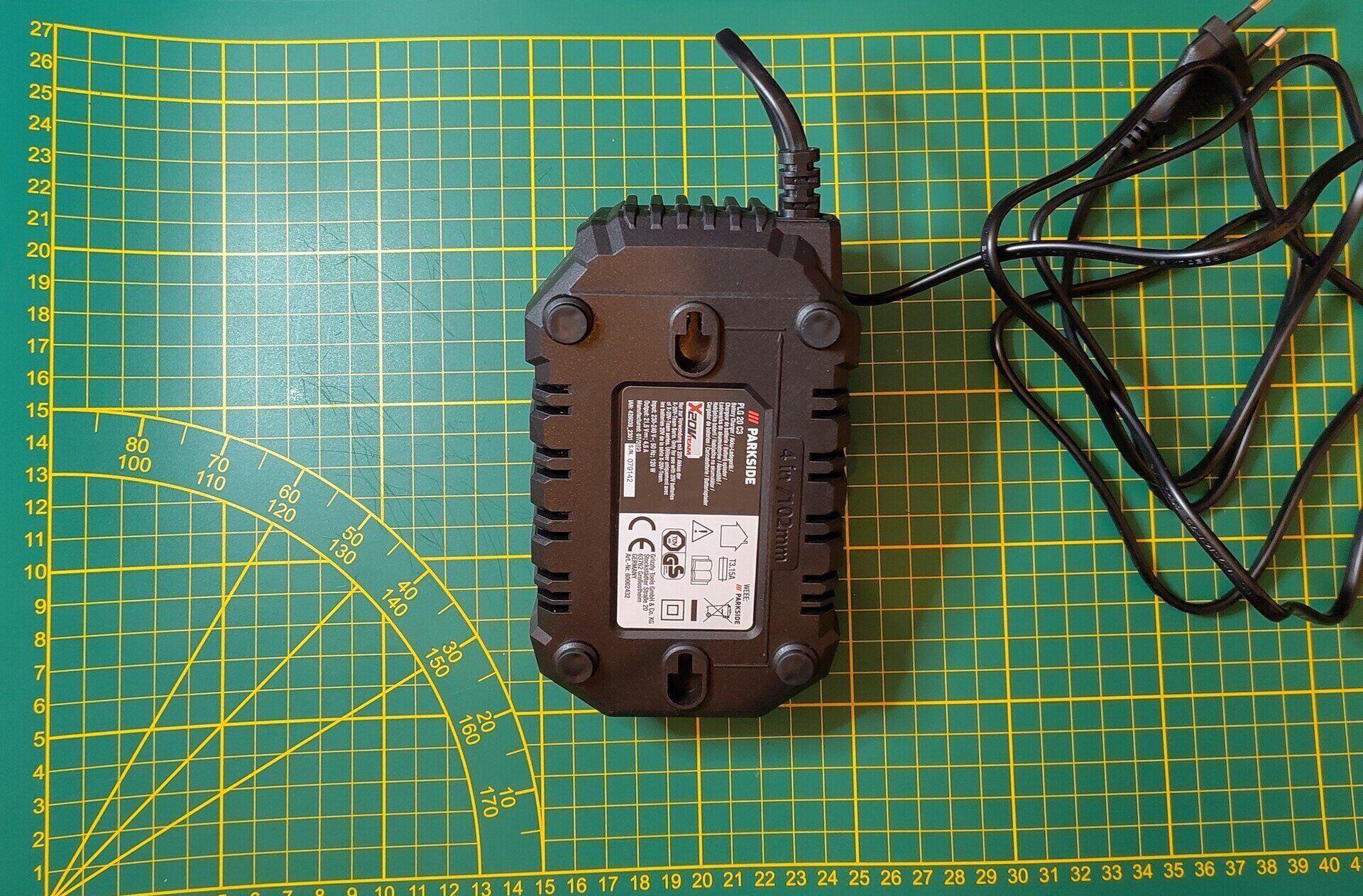
Remove the rubber pads covering the screw holes, you can use a small screwdriver if you want, but I found you can easily remove them with just your fingers. Put them somewhere save, so you can put them back later.
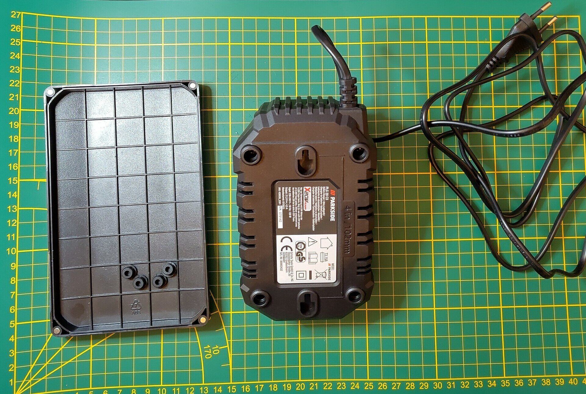
Now with the rubber pads removed we can now access the screws, remove them with a phillips head screwdriver, and once again put them somewhere save.
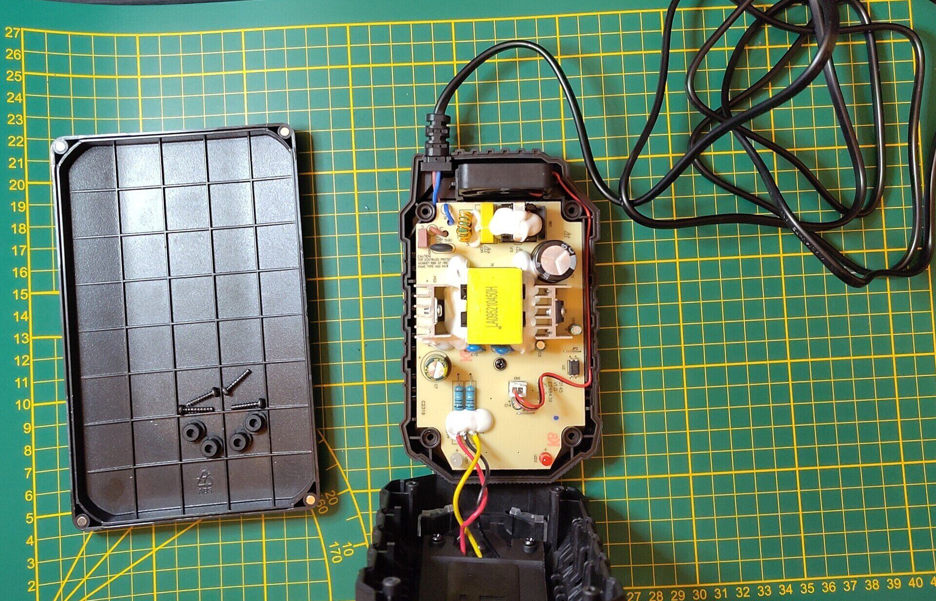
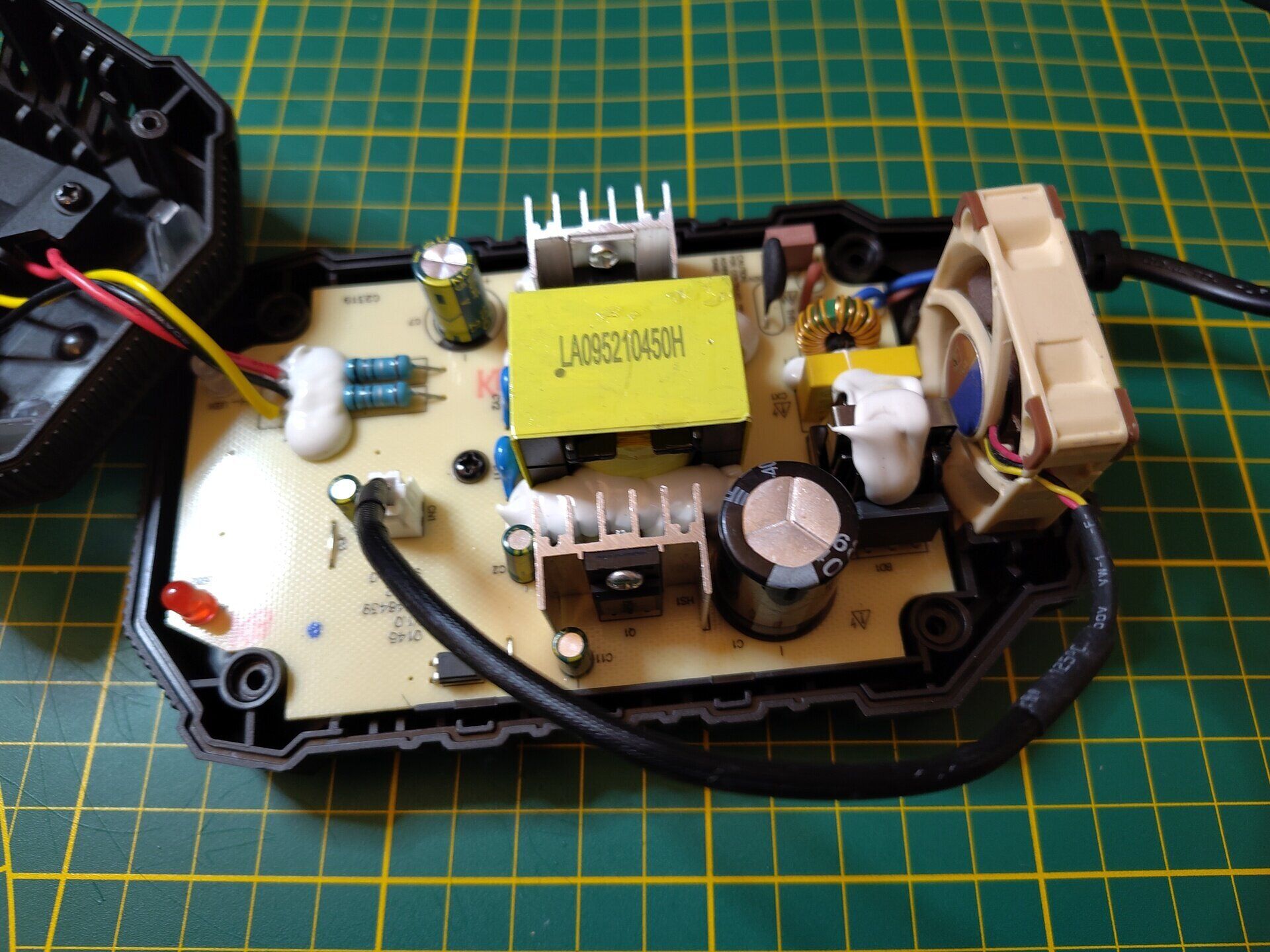
With the screws removed we can open up the charger by turning the charger around so the top is facing you, lift the top and remove it. Be careful though, the charging connection circuit is still connected to the top shell, so don’t break the wires or connections when opening them up. We can leave the charging connection circuit attached while doing this mod, we can just leave it to the side.
With the top shell moved to the side we can now see stock fan sitting next to the mains voltage input. The air flows over the main parts of the motherboard and the heat sinks and will come out at the air vents at the edges.
Step 2 - Remove the stock fan
Now we will remove the stock fan, lift the fan wire out of the little channel on the right edge. After lifting this fan wire out you’ll want to disconnect the JST connector. The fan is push fit so with the wire removed you can lift the fan.
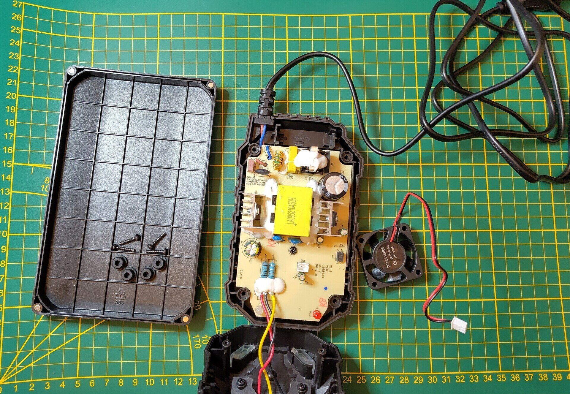
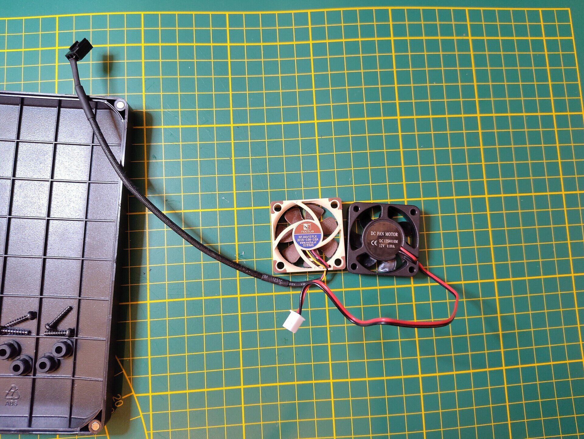
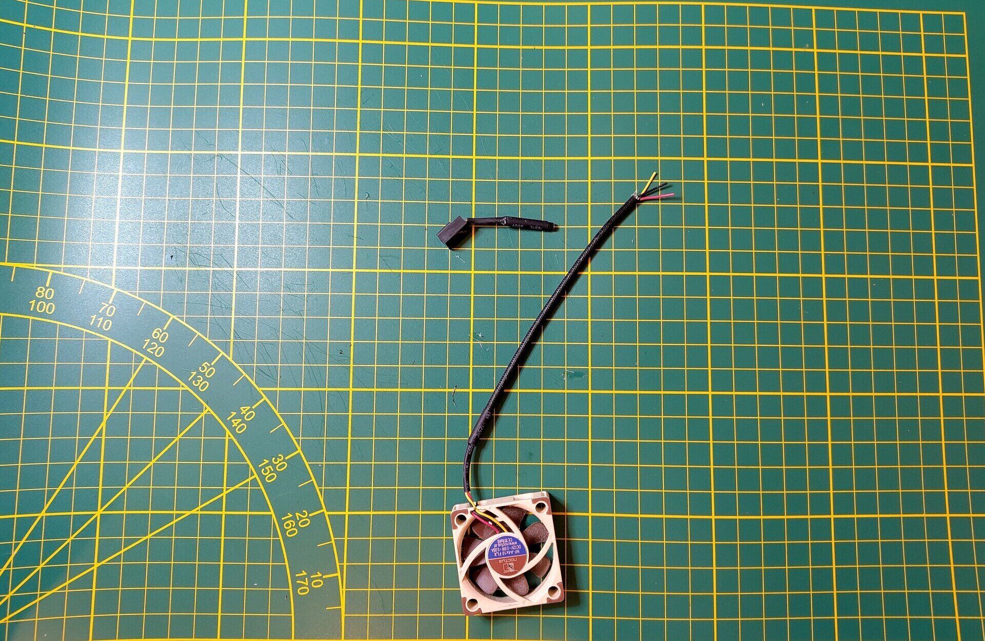
Here you can see the two fans next together, as you can see both are 40x10 mm and have 12V. Now manufactures are known to change up their parts from time to time, so as a sanity check, verify the stock fan is also running on 12V. This is to prevent that in case of a revision you accidentally blow up your replacement fan.
Step 3 - Prepare the replacement fan
Alright with the fan ready we will start by snipping off the current connector, I recommend keeping some room around the connector, so there is enough cable left to reuse it for a future project.
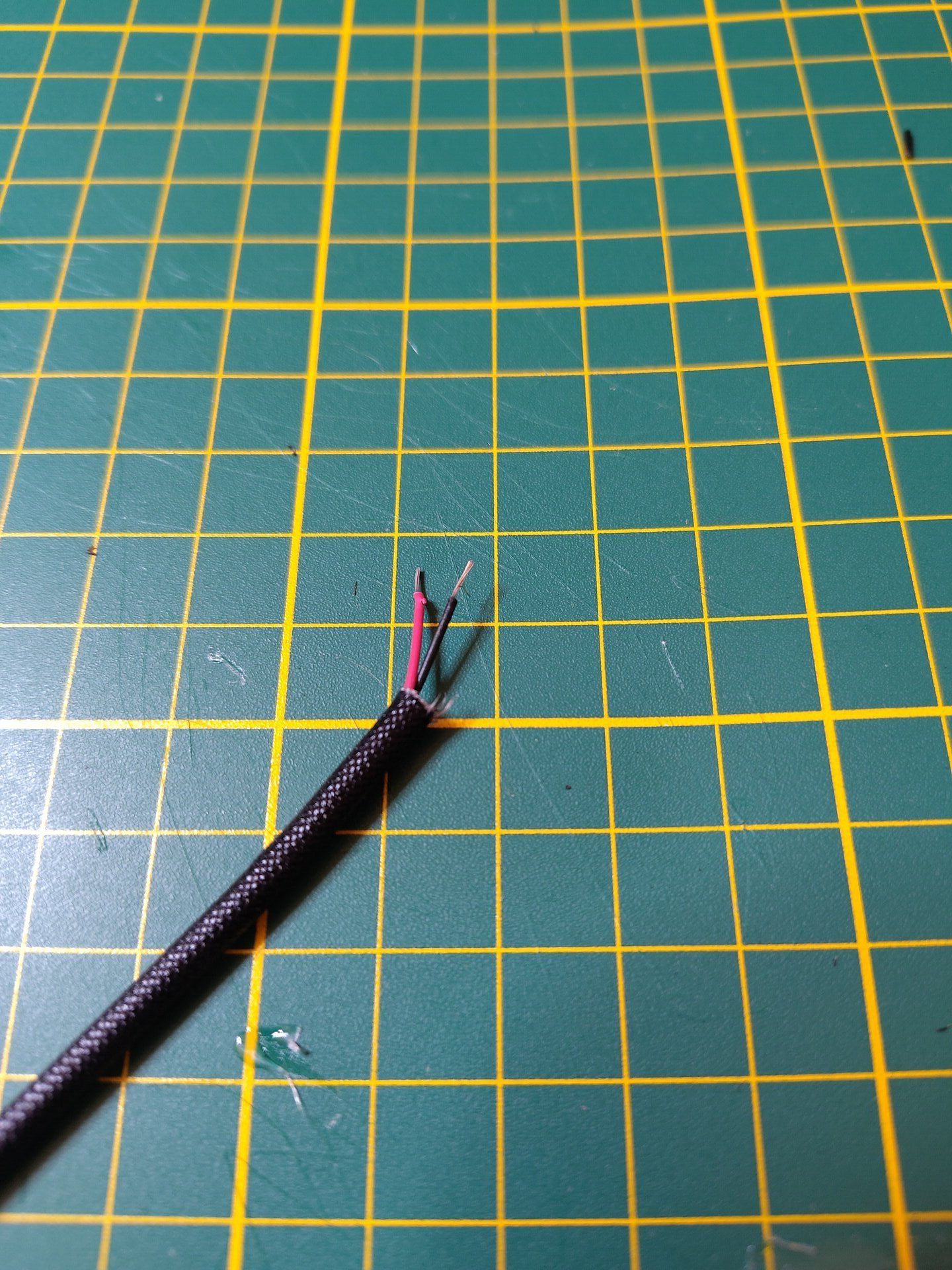
Time to strip the wires, let’s first remove some of the outer sleeve, be careful you don’t want to damage the inner isolation of the wires inside. With the sleeve out of the way you’ll only need to strip the positive (red) and negative (black) leads, you can leave the other ones untouched for now. Strip off around 3-4 mm of the isolation, a bit more is fine, we will get it to the right length when we are going to crimp on the JST connector.
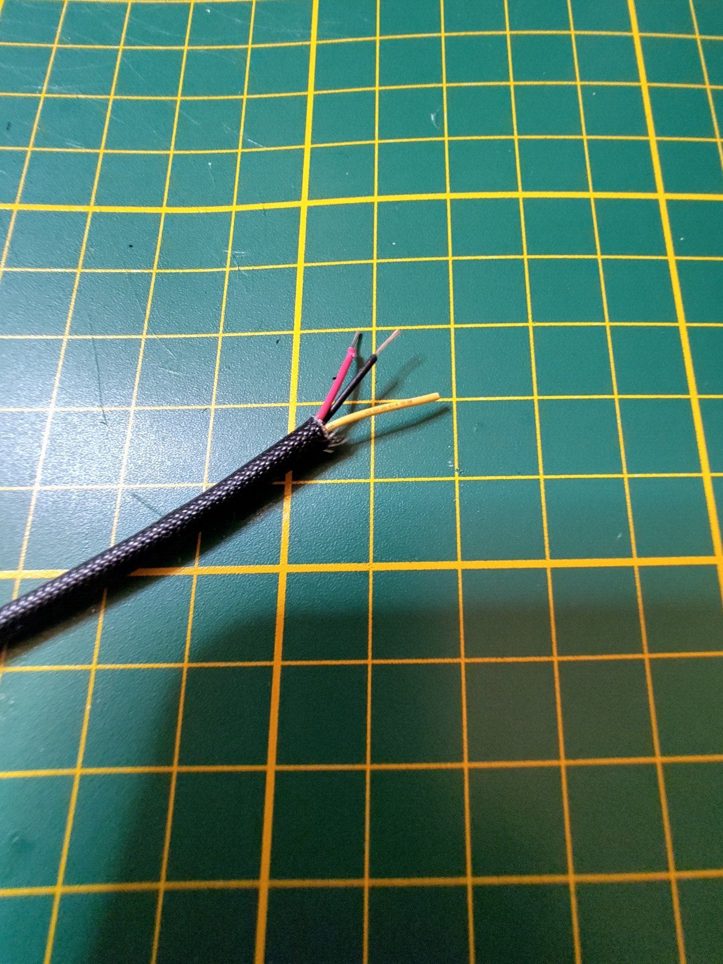
The other wires are now still left as you can see, I say wires because you might have a fan with PWM included as well as the Tachometer wire. We won’t need any of those so we can snip them off at the same length of our sleeve.
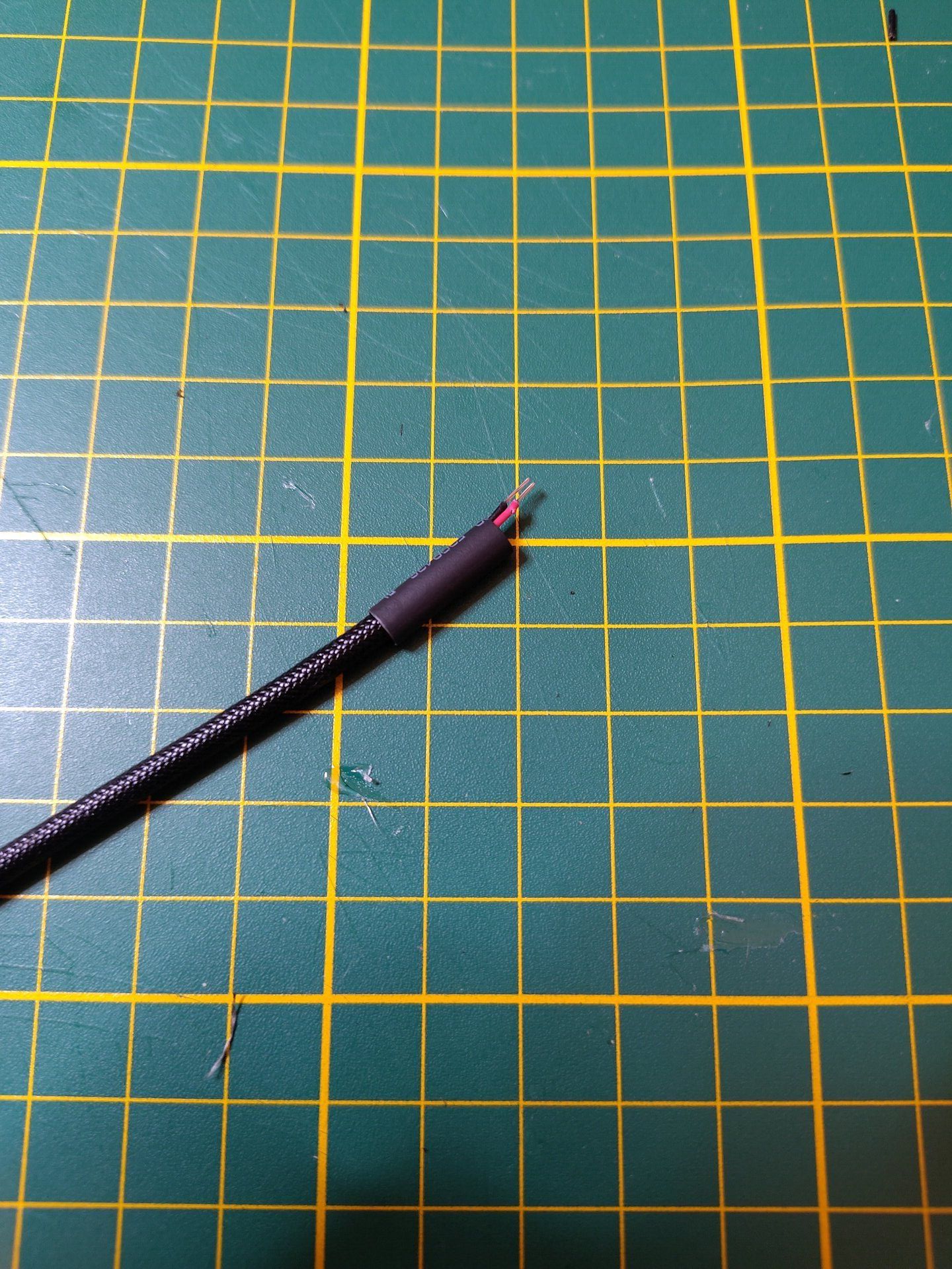
To neatly clean everything up we will now add some shrinkwrap to our cable, for the diameter pick the smallest one that still fits over the cable and sleeve. As for the length try to cut it a little longer then the removed sleeve, so it easily can covert part of the sleeve and all the exposed wires.
Step 3.1 - Crimping on the JST connector
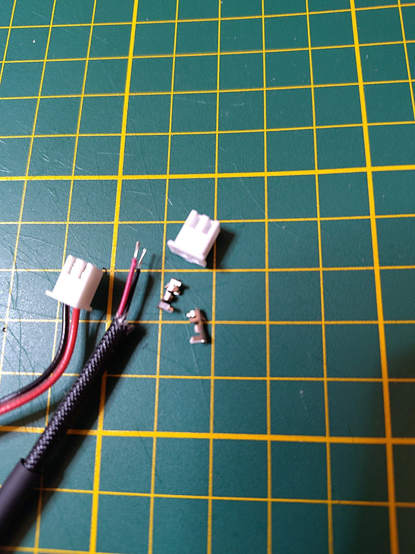
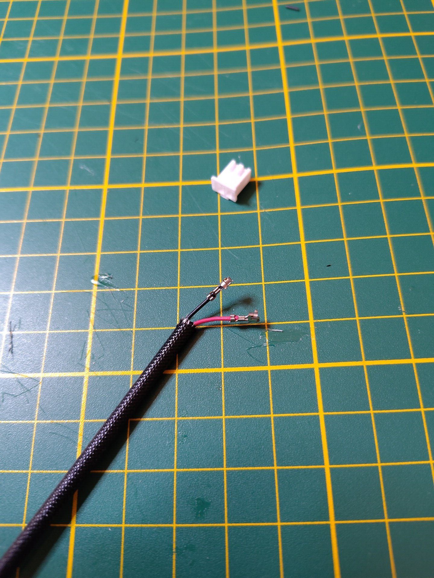
Now get out your JST crimping tool as well as one JST shell with room for two pins, and of course two JST connectors to crimp on the exposed terminals. As you can see I have the stock fan connector in reach as a reference, as to not make a mistake with the positive and negative lead positions. So in the end just make sure your wire matches the one of the stock fan you pulled out, it should be the same as the one you see pictured here.
With the preparations out of the way comes time for delicate work for crimping a JST connector, this is a bit intricate of a process, I recommend you look up a guide for it. I sadly don’t have one for you (yet), but there are some good videos for it out there, I think I used this one to learn it. If something goes wrong don’t worry just remove the failed crimp and expose the copper wires and try again.
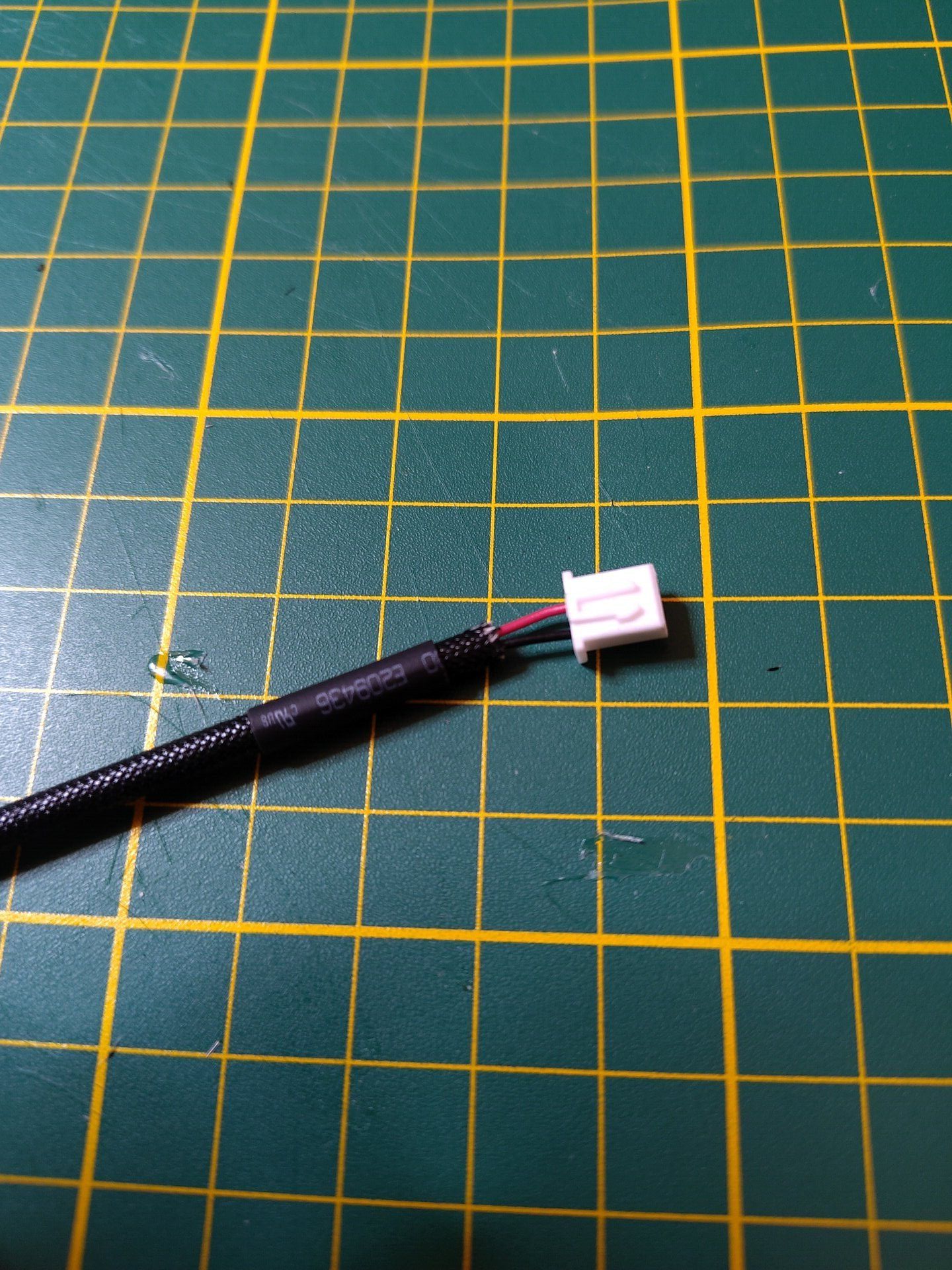
Having arrived here I assume everything went well, at least in the end, and now is the moment to put on the actual JST connector shell on. Recall the video I just shared, he also shows how to put in the crimps into the shell. Remember we want to match the wire as we can see on the stock fan. So slot in the wires correctly and give it a little tug to ensure the connectors are well seated into the shell.
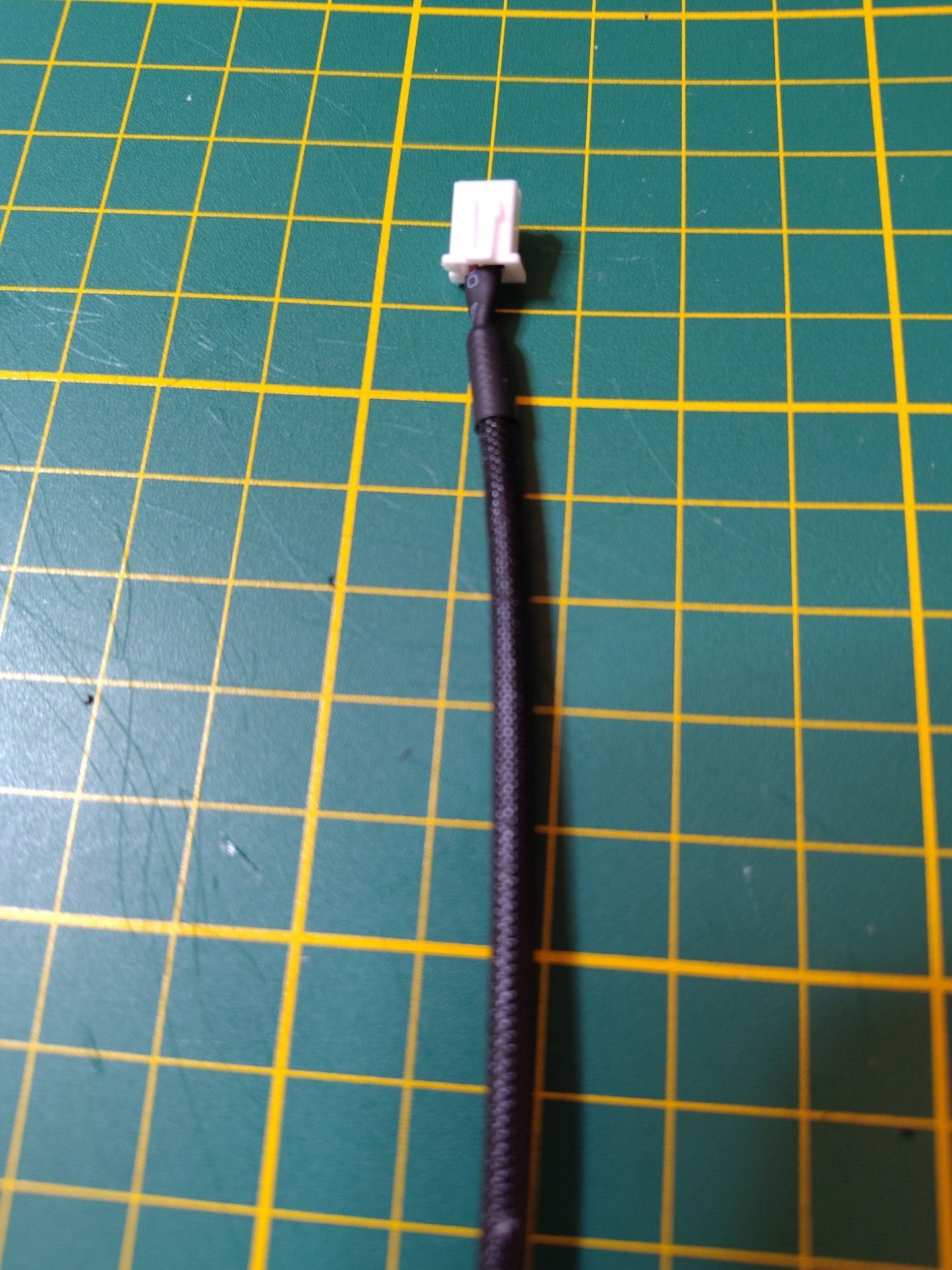
Alright we’re almost done with the new wire, the last part is the finishing touch and that is covering the loose wires with our shrinkwrap that was on the cable. Move the shrinkwrap completely up to the JST connector shell and get a heat source, if you have a heatgun now is the time to have that, else either get a lighter or matches. With your heat source we want to heat the shrinkwrap evenly and ensure that we don’t burn it. Keep going until you have nice looking wrap as you can see in the picture below.
That was the last step of creating our new fan, this was also the most involved step of this whole process, so we can say the mod is almost done now with this out of the way.
Step 4 - Place the replacement fan into the chassis
Remember I said that the fan was push fit, that becomes a little more litteral with the Noctua replacement, the dampners make for the fan to be a little tight. So it will require a small but even amount of force to fit the fan in, upside, the fan will definetely not go anywhere.
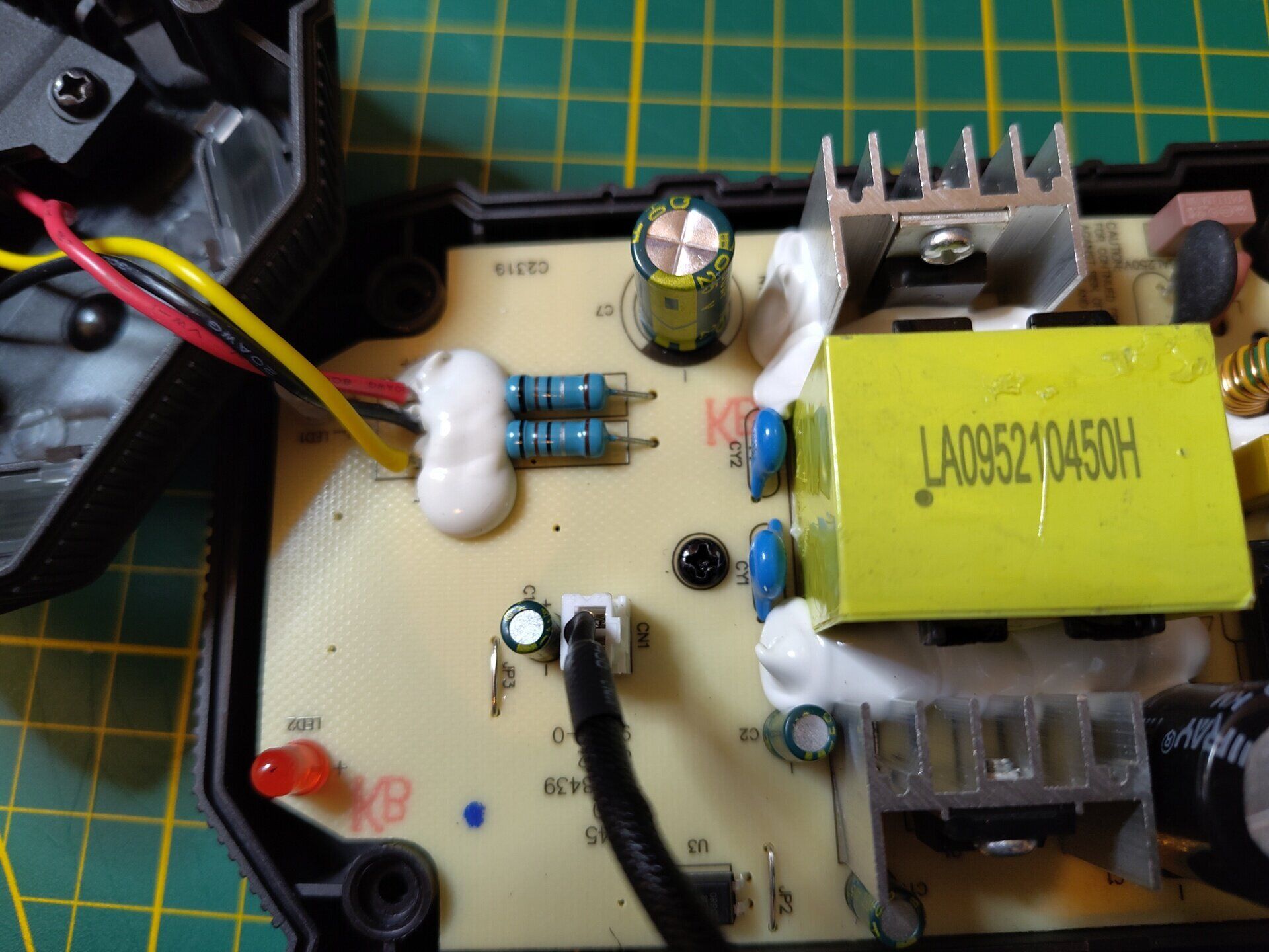
Now when it comes to the cable, it won’t through the existing cable cutout used by the stock fan, but this is fine. You can see the large capacitor on the board (the large cylinder next to the heatsink) those are not supposed to get hot at all, if it does, that is a problem all in of itself. So we can use the cap and the screw guide next to it to route the cable through, there it will be neatly out of the way of the airflow of the fan.
With the fan seated in and connected up to the fan header on the motherboard do a quick visual inspection of the connector. Make sure the shell is inserted completely into the header, also verify the individual wire connectors are still neatly in place and are not pushed out due to a bad crimp.
Step 5 - Put the charger back together
Time for the last step, put it all back together, put the top shell back on the charger, making sure the fan wire is routed as I mentioned above. With the assembly back in one piece you can put the screws back in and then the rubber pads covering the screw holes.
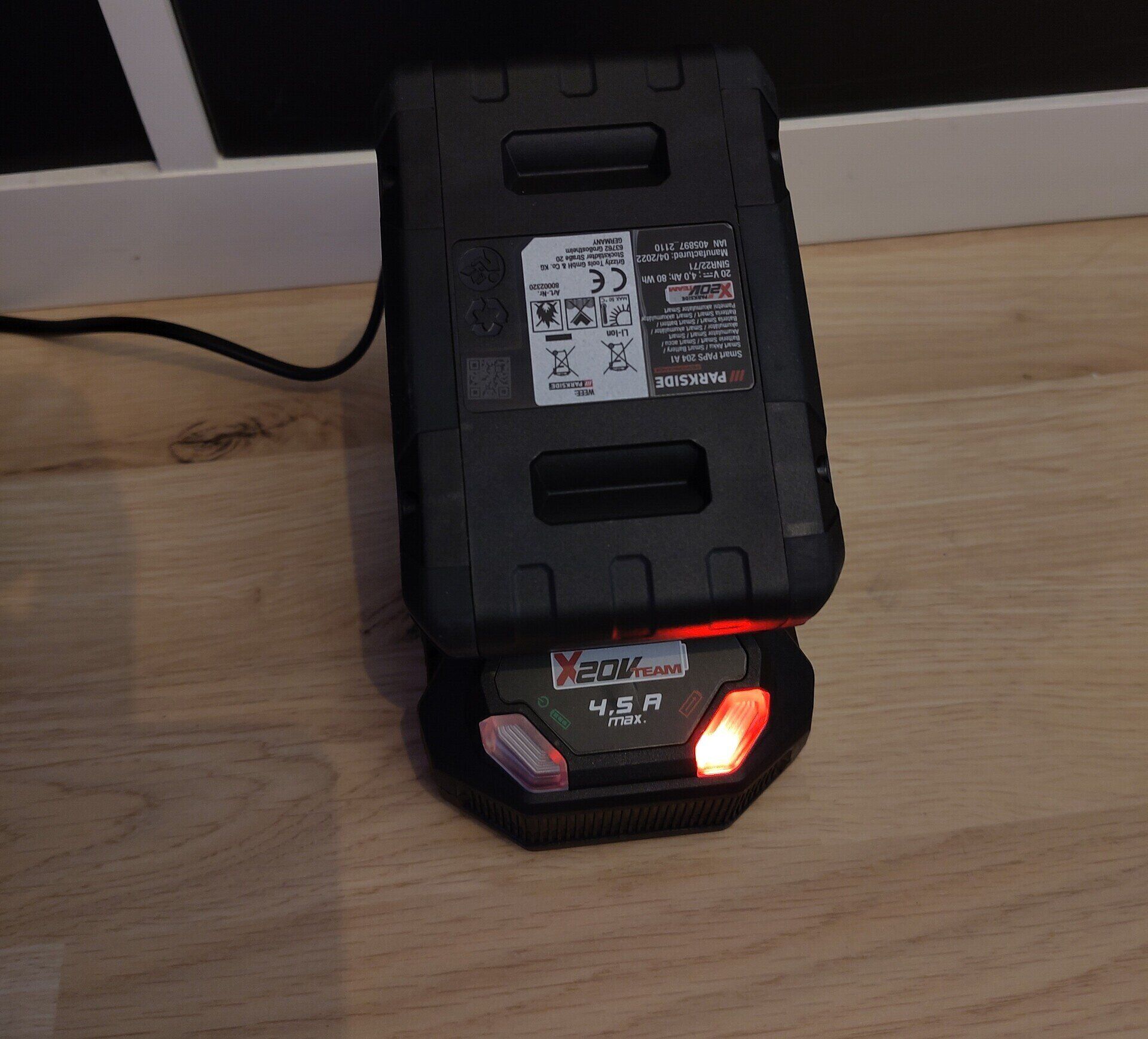
And just like that you have a silent Parkside 20V charger, so go ahead and put an empty battery on it to test it all out. I at first thought I might have made a mistake with putting everything back together because I heard nothing. To verify the fan working I had to pick it up and put my ear to the fan intake to hear the soft fan noise coming from it.
A quick side note, the fan in the charger has a small control circuit, this means that if your battery is full the fan will be turned off completely. So if you don’t hear anything at all, before taking everything apart again, double-check the battery is actually charging or not.
Done
Now I hope you have a functional charger that is very silent compared to a stock one shipped by Lidl. As I mentioned I got my Noctua fan second hand for this, you can also see that by how dusty it still is even after cleaning. Using a new one might be a bit of steep investment, doubling the price of your charger in most cases, so I recommend also looking out for a used one.
Something I want to try is getting some cheap Sunon or Winsinn fans that run on 24V and test their noise levels at 12V, if they run at that voltage at all. Now I’ve used those before and I didn’t find them particularly silent, even at lower voltages, so that might be an effort leading nowhere.
But if you have an idea for cheaper silent fans (Scythe sadly discontinued their 40x10mm fan) that are cheaper but almost as silent contact me. If you have any other improvements for this guide just e-mail me.